►Product name: Force Sensitive Resistor FSR402 Film Pressure Sensor Weight Sensor
►Keyword: force Sensitive resistor,FSR,weight sensor,FSR402,film pressure sensor.
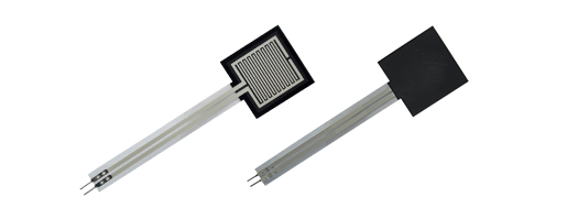 ①Model:R38-3500
②Type: Single point force sensor
③Use: To measure continuously changing force at a point of use
④Principle of work: Within the range,the greater the pressure applied,the smaller the sensor resistance have
►What is Force Sensing Resistor (FSR)?
Force sensing resistor or we call force sensor, can be defined as a special type of resistor which exhibits a decrease in resistance with an increase in the force applied to the active sensing surface. The force sensing resistor is generally supplied as a polymer sheet or ink which is applied as screen printing. Both the electrically conducting and non-conducting particles are present on this sensing film. If force is applied to a surface of sensing film, then the particles touches the conducting electrodes and thus resistance of the film changes. There are several resistive based sensors but force sensing resistors operate satisfactorily in difficult environments and also requires a simple interface compared to other resistive based sensors.
Even though there are various types of force sensors, the force sensing resistors are having several advantages such as thin size (less than 0.5mm), very low cost and also good shock resistance. The only disadvantage of FSR sensors is low precision, there will be approximately 10% or more difference in measurement results. So it can’t be used as weighing equipment. It acts as a reaction of force rather than as an accurate reading of pressure.
►Applications of Force Sensing Resistor
There are numerous applications for force sensing resistors in various fields such as motion analysis systems, automobiles like car sensors, resistive touch-pads, musical instruments, Medical bed, Measurement of bite force of teeth, die pressure measurement,and so on. It may be used wherever pressure measurements and data collection are required.
►Relevant Parameter
Dimensions: customizable, preferably within 400*600mm.
Resistance value range (maximum) : without pressure, resistance > 2 MΩ
Range (single point) : 20g~2KG, 50 g ~ 5 kg, 100 g ~ 10 kg
Response time: 10ms
Test voltage: DC3.3V/DC 5V
Working temperature: - 20 to 60 ℃
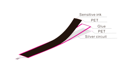
►Structure diagram
This FSR is specifically designed to test the degree of bending of the sensor, the degree of bending, and the size of the contact area has a great impact on the resistance change. Generally used for medical mattresses, seat cushions, game gloves and other aspects.
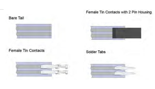
 ►Connector type
 ►Testing a FSR
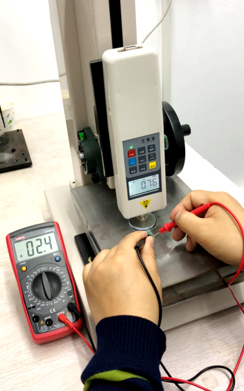
The easiest way to determine how your FSR works is to connect a multimeter in resistance-measurement mode to the two tabs on your sensor and see how the resistance changes. Because the resistance changes a lot, a auto-ranging meter works well here. Otherwise, just make sure you try different ranges, between 1 Mohm and 100 ohm before giving up.
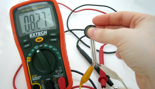 If you have force applied equipment, that is better, like below:
 ►How to connect FSR
FSRs are often a polyester with conductive material silk-screened on. That means they're plastic and the connection tab is crimped on base polyester material. The best way to connect to these is to simply plug them into a breadboard.
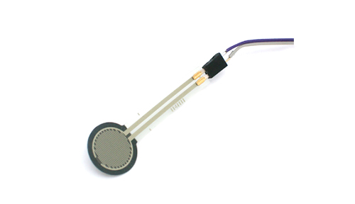
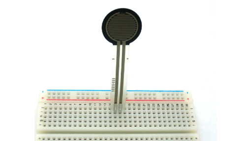 or use a clamp-style connector like alligator clips, or a female header.
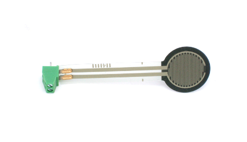
or a terminal block such as Phoenix #1881448
 ►How to use FSR
Analog Voltage Reading Method
The easiest way to measure a resistive sensor is to connect one end to Power and the other to a pull-down resistor to ground. Then the point between the fixed pulldown resistor and the variable FSR resistor is connected to the analog input of a microcontroller such as an Arduino (shown).
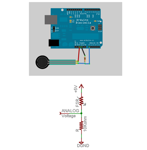 For this example we are showing it with a 5V supply but note that you can use this with a 3.3v supply just as easily. In this configuration the analog voltage reading ranges from 0V (ground) to about 5V (or about the same as the power supply voltage).
The way this works is that as the resistance of the FSR decreases, the total resistance of the FSR and the pulldown resistor decreases from about 100Kohm to 10Kohm. That means that the current flowing through both resistors increases which in turn causes the voltage across the fixed 10K resistor to increase.
Force
(lb) |
Force
(N) |
FSR Resistance |
(FSR+R)ohm |
Current thru FSR+R |
Voltage across R |
| None |
None |
lnfinite |
lnfinite |
0 mA |
0V |
| 0.04lb |
0.2N |
30 Kohm |
40 Kohm |
0.13 mA |
1.3V |
| 0.22lb |
1N |
6 Kohm |
16 Kohm |
0.31 mA |
3.1V |
| 2.2lb |
10N |
1 Kohm |
11 Kohm |
0.45 mA |
4.5V |
| 22lb |
100N |
250 ohm |
10.25 Kohm |
0.49 mA |
4.9V |
This table indicates the approximate analog voltage based on the sensor force/resistance w/a 5V supply and 10K pulldown resistor. Note that our method takes the somewhat linear resistivity but does not provide linear voltage! That's because the voltage equation is:
Vo = Vcc ( R / (R + FSR) )
That is, the voltage is proportional to the inverse of the FSR resistance.
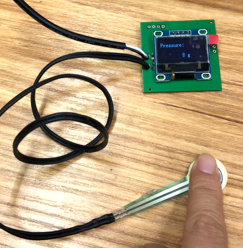
An example of reading the pressure as below:
 ►Simple Demonstration of Use
Wire the FSR as same as the above example, but this time let’s add an LED to pin 11.
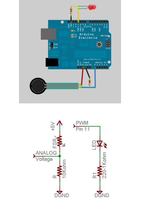 This sketch will take the analog voltage reading and use that to determine how bright the red LED is. The harder you press on the FSR, the brighter the LED will be! Remember that the LED has to be connected to a PWM pin for this to work, we use pin 11 in this example.


