►What is Force Sensing Resistor (FSR)?
Force sensing resistor or we call force sensor, can be defined as a special type of resistor which exhibits a decrease in resistance with an increase in the force applied to the active sensing surface. The force sensing resistor is generally supplied as a polymer sheet or ink which is applied as screen printing. Both the electrically conducting and non-conducting particles are present on this sensing film. If force is applied to a surface of sensing film, then the particles touches the conducting electrodes and thus resistance of the film changes. There are several resistive based sensors but force sensing resistors operate satisfactorily in difficult environments and also requires a simple interface compared to other resistive based sensors.
Even though there are various types of force sensors, the force sensing resistors are having several advantages such as thin size (less than 0.5mm), very low cost and also good shock resistance. The only disadvantage of FSR sensors is low precision, there will be approximately 10% or more difference in measurement results. So it can’t be used as weighing equipment. It acts as a reaction of force rather than as an accurate reading of pressure.
►Applications of Force Sensing Resistor
There are numerous applications for force sensing resistors in various fields such as motion analysis systems, automobiles like car sensors, resistive touch-pads, musical instruments, Medical bed, Measurement of bite force of teeth, die pressure measurement,and so on. It may be used wherever pressure measurements and data collection are required.
►Relevant Parameter
Dimensions: customizable, preferably within 400*600mm.
Resistance value range (maximum) : without pressure, resistance > 2 MΩ
Range (single point) : 20g~2KG, 50 g ~ 5 kg, 100 g ~ 10 kg
Response time: 10ms
Test voltage: DC3.3V/DC 5V
Working temperature: - 20 to 60 ℃
►Structure diagram
This FSR is specifically designed to test the degree of bending of the sensor, the degree of bending, and the size of the contact area has a great impact on the resistance change. Generally used for medical mattresses, seat cushions, game gloves and other aspects.
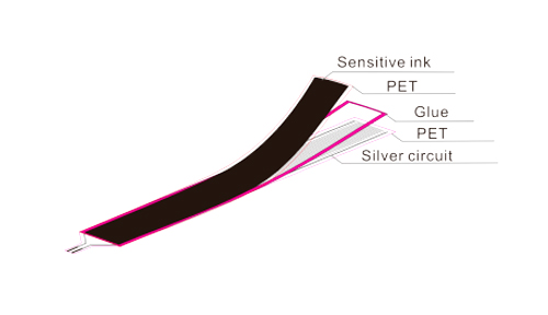 ►Connector type
 ►Testing a FSR
The easiest way to determine how your FSR works is to connect a multimeter in resistance-measurement mode to the two tabs on your sensor and see how the resistance changes. Because the resistance changes a lot, a auto-ranging meter works well here. Otherwise, just make sure you try different ranges, between 1 Mohm and 100 ohm before giving up.
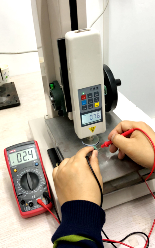
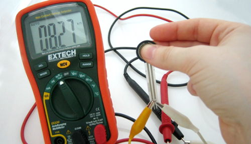 If you have force applied equipment, that is better, like below:
 ►How to connect FSR
FSRs are often a polyester with conductive material silk-screened on. That means they're plastic and the connection tab is crimped on base polyester material. The best way to connect to these is to simply plug them into a breadboard.
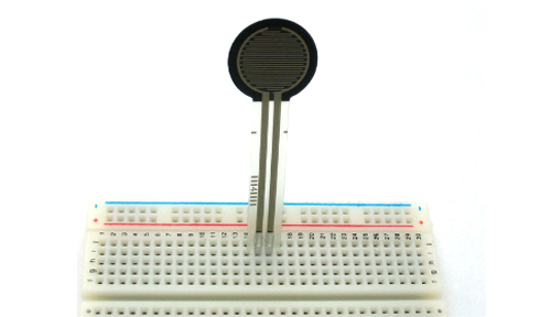 or use a clamp-style connector like alligator clips, or a female header.
 or a terminal block such as Phoenix #1881448
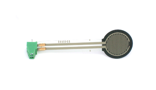 ►How to use FSR
Analog Voltage Reading Method
The easiest way to measure a resistive sensor is to connect one end to Power and the other to a pull-down resistor to ground. Then the point between the fixed pulldown resistor and the variable FSR resistor is connected to the analog input of a microcontroller such as an Arduino (shown).
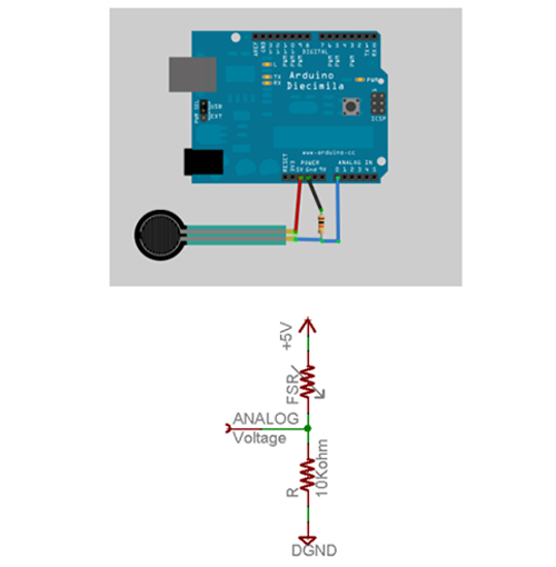 For this example we are showing it with a 5V supply but note that you can use this with a 3.3v supply just as easily. In this configuration the analog voltage reading ranges from 0V (ground) to about 5V (or about the same as the power supply voltage).
The way this works is that as the resistance of the FSR decreases, the total resistance of the FSR and the pulldown resistor decreases from about 100Kohm to 10Kohm. That means that the current flowing through both resistors increases which in turn causes the voltage across the fixed 10K resistor to increase.
Force
(lb) |
Force
(N) |
FSR Resistance |
(FSR+R)ohm |
Current thru FSR+R |
Voltage across R |
| None |
None |
lnfinite |
lnfinite |
0 mA |
0V |
| 0.04lb |
0.2N |
30 Kohm |
40 Kohm |
0.13 mA |
1.3V |
| 0.22lb |
1N |
6 Kohm |
16 Kohm |
0.31 mA |
3.1V |
| 2.2lb |
10N |
1 Kohm |
11 Kohm |
0.45 mA |
4.5V |
| 22lb |
100N |
250 ohm |
10.25 Kohm |
0.49 mA |
4.9V |
This table indicates the approximate analog voltage based on the sensor force/resistance w/a 5V supply and 10K pulldown resistor. Note that our method takes the somewhat linear resistivity but does not provide linear voltage! That's because the voltage equation is:
Vo = Vcc ( R / (R + FSR) )
That is, the voltage is proportional to the inverse of the FSR resistance.
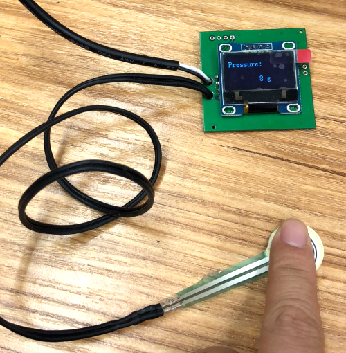
An example of reading the pressure as below:
 ►Simple Demonstration of Use
Wire the FSR as same as the above example, but this time let’s add an LED to pin 11.
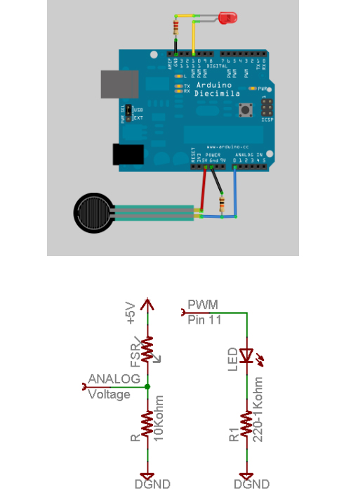 This sketch will take the analog voltage reading and use that to determine how bright the red LED is. The harder you press on the FSR, the brighter the LED will be! Remember that the LED has to be connected to a PWM pin for this to work, we use pin 11 in this example.
►Common questions for using FSR
1)Are you able to provide technical support and guidance throughout the project?
Yes, we have very experienced engineering team.
2)Is there any discount for purchase?
The more the quantity, the greater the discount.
3)Do you have a return policy?
Generally within 48 hours, the sensor without external deformation (damage), can be returned or replaced.
4)What is the sensor made of?
Polyester as base material, silver ink as conductor of electricity, special resistance ink for force sensing area.
5)Are sensors available for different shapes, lengths and sizes?
Yes, we provide custom service.
6)What is the resolution of the sensor?
The sensor can be amplified into an analog voltage output. The general resolution is determined by an electronic conditioning circuit.
7)How does the sensor change with force?
Generally speaking, the greater the general force, the smaller the resistance.
8)What is the maximum overload of the sensor?
It depends on the exact sensor design.
9)What is the lifetime of the sensor?
The life of the sensor (durability) rest with many factors: load weight/force applied, material for sensing surfaces, the direction of the applied force (shear force has a great influence on the life of the sensor).
10)Under what conditions will there be damage to the sensor? Temperature over 78 ℃, Soak in water (the top and bottom layers of the sensor are glued together and will come off), Contact with hard and sharp object, Shear force, Pressure sensor, Any force greater than the maximum load.
11)Can senors be folded?
The sensor is flexible, but the sensor area cannot be folded, because there will be shear force.The conductive part can be bent, but generally not more than 90 degrees, otherwise the conductive silver layer will fracture.
12)Can I stick the sensor to the surface?
Yes, we can supply the sensor with rear adhesive. But you better not stick the sensor directly on surface. Usually there will be something placed under the sensing area to do the test. And it is necessary to make sure the adhesive is covering very flatly on the surface.
13)Why is it necessary to amplify the circuit to read the value of pressure for some sensors? The sensor is actually a resistor that change according to the pressure, but linear is not good, so we can make pressure value and voltage change form a linear output by amplifying the circuit.
14)What is the range of resistance of the sensor?
It depends on the exact design.
15)How to connect the sensor after cutting?
There are two methods, one is to use the appropriate binding machine, and then install two pins out of contact, another is to use conductive epoxy resin to bond the connector to the wire.
16)Why "train" the sensor in its first use?
The output of the sensor is easy to change when it is used for the first time. In order to get good repeatability effect on time, the sensor is usually pressed with 110% load for several times before calibration.
17)What is the margin of error without "training" the sensor?
Generally greater than 5%. So it is recommended to "train" the sensor before using it.
18)How is the sensor calibrated?
It is to use weights or pressure meters to add a standard force to the sensor, set up the relationship between the output voltage and the corresponding value of the force applied.
19)It has been calibrated once. How long will it be without calibration?
Usually a few weeks. Frequent calibration can improve the accuracy of measurement.
20)Why calibrate the sensor?
It’s a very important step. There will be slight differences between different sensors when they leave the factory, and the environment during calibration and actual measurement shall be consistent, which can greatly improve the accuracy of actual measurement and reduce errors.
21)Do you need a spacer/gasket for the measurement? How to choose the material and size of spacer/gasket?
Generally in the measurement of a relatively large force or a relatively small point of force, or the compression surface is more severe when adding gasket can ensure that the pressure is uniform, and does not damage the sensor. Gasket area is generally in the sensing area of 70% to 95%, the material with hard plastic is the best.
22)How sharp a force can the surface of the sensing area receive?
That force that may puncture the sensor or resulting in indentation on sensor should be avoided, generally we need to add gasket upon sensor.
23)What pressure plane is ideal?
A flat, smooth surface.
24)Does humidity affect the sensor?
Experiments have been done in the high humidity environment, and the response is within the normal range.
25)Is the sensor affected by noise?
Yes, the sensor will absorb a little noise, preferably to process it in the circuit.
26)Are the sensors affected by magnetic fields and radiation?
Little or no effect from the magnetic field. No radiation was recorded.
27)What is the maximum force that the sensor can withstand?
As long as the pressure is less than 10,000 psi, it can be down to a few thousand pounds.
28)How long will it take to customize the sensor?
Depending on how easy it is, it usually takes 3-5 weeks.
29)What’s MOQ for sensor?
The minimum quantity is usually 1000pcs.
30)Can you customize sensors for the ELF system?
Yes.
31)What is the approximate cost of a custom sensor?
Each requirement is different. Generally, the cost varies according to the complexity, size, range and quantity of customization. Please send the design file and requirement to get quote.


