►SMT membrane switch
SMT membrane switch is also called LED membrane keypad,SMT membrane keyboard or SMT membrane button.
►Similar products

 ►Basic info
SMT membrane switch is membrane switch that resistors, LED lights, chips and other SMD components can be mounted on.
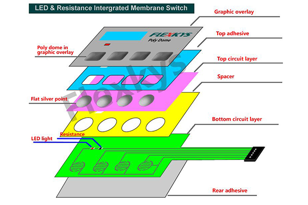
►Structure presentation
►Basic info
SMT membrane switch is membrane switch that resistors, LED lights, chips and other SMD components can be mounted on.
►Structure presentation
 ►Basic info
Components such as resistors, LED lights, sensors, and even chips can be mounted on membrane switch circuit.Membrane switches are not just buttons to human - computer any more.Based on different circuit materials, the membrane switch can integrate more electronic functions, even move all the components originally placed on the PCB to the membrane switch. Product design flexibility has more choices which save the internal space of the machine and also reduce the final product manufacturing cost.
►Basic info
Components such as resistors, LED lights, sensors, and even chips can be mounted on membrane switch circuit.Membrane switches are not just buttons to human - computer any more.Based on different circuit materials, the membrane switch can integrate more electronic functions, even move all the components originally placed on the PCB to the membrane switch. Product design flexibility has more choices which save the internal space of the machine and also reduce the final product manufacturing cost.
In recent years, with the continuous progress of science and technology, carbon printed resistance can be printed on the flexible circuit directly .It replace the original printed resistance which makes the membrane switch design be more convenient.
►Normal material
3 types of circuits that can integrate electronic components
①Silver printed circuit: can mount LED,normal resistance,printed resistance
②FPC circuit: can mount LED,normal resistance ,chip(thickness is lower than1mm )
③PCB circuit: can mount LED,normal resistance ,chipNote: The normal thickness is lower than 1.5mm,so the electric components on circuit thickness is not higher than 1mm
►Working environment
Temperature: -20~60℃
Humidity: 40℃,RH<90%
►Electrical performance
Circuit voltage: DC 50V MAX (others need meet components)
Circuit current: 200mA MAX for silver print circuit; 1A MAX for FPC/PCB
Closed circuit resistance: normally <10 ohm(details see products designing and circuit length)
Button working life: >50million times
Response time: <10 mS
►Notice on mounting and operating
①Clean up the surface where the switch is bonded and make sure it is flat ,without rust, oil and dust.
②Compare the size to membrane switch where need be stick ,check if position is correct.
③Tear off 10mm length of the bottom release paper from side.
④Put the tail through the back board. Please do not pull the tail with force. The minimum bending radian of the lead wire is R=2mm. The hold edge must smooth in case of damaging the tail.
⑤Align the panel with the sticking place and press on the fixed part, then slowly remove the rest release paper and flat the panel.
⑥The stick process is finished in one time.Switch can not be repeated stick.
⑦Please make sure the bending angel of panel is lower than 15 degree when sticking.
⑧Please do not pull the connector so hard when in connection. For female connector, please hold the house when in connector.
⑨Do not pull the lead wire directly. For FPC( Flexible printed circuits) structure, please unlock the socket before plugging.
⑩Note:To assure the switch life , please put it on the table flatly when testing the hand feeling. Do not pinch the button when holding it on hand.